Navigatie overslaan

Category Archives: Tips & Trics

The Question:

Hi, 

Many a time where you happened to want to create a library but found it too cumbersome because the record information must be written directly in the resource manager rather than a spreadsheet?

Is it possible to write existing record information inside of a symbol to the symbol definition please? This would tremendously expedite symbol and library creation.


First of all you need to know that the Symbol in your drawing is an Instance (a placeholder, a locus, if you like) that redirects the program to the Symbol Definition in the Resource Manager when it needs to draw the Symbol. Everything you do with the Instance in the layer doesn’t affect the definition. (Editing seems to contradict that, until you realise the program simply brings you to the definition to edit). The Instance can have a record attached, but that doesn’t automatically go for the Definition. If a Definition has a record the Instance automatically has the same record and will initially show the same (Default) data. Changes to the data in the Record of the Instance will NOT be brought to the Record of the Definition.

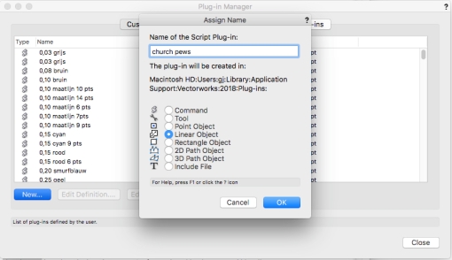
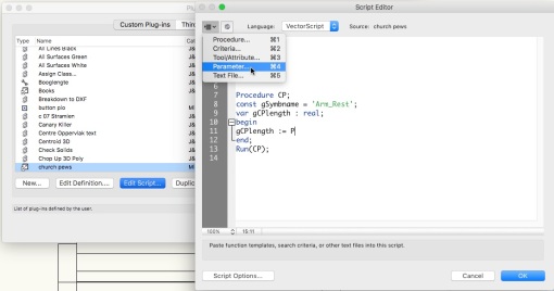
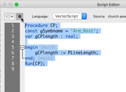
So when you setup a library document with a lot of symbols with records you have to edit the default values of the records at Definition level. Instead of bringing all data from the instances to their definitions by hand we can of course write a little script that does it for you:

Move Rec from Inst to Def.vsm

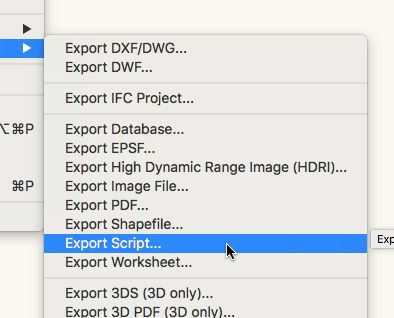
It is a plug-in menu command.

  1. Unzip
  2. Place into Plug-Ins folder inside User folder *
  3. Restart Vectorworks
  4. In Vectorworks go to Menu bar Tools:Workspaces:Edit The current Workspace
  5. Drag the menu from left to right in a menu of your choice

To find the User folder

  1. Go to the Vectorworks preferences
  2. Click the Tab called User Folder
  3. Click either “Reveal in Finder” or “Explorer”

If you select no objects, the command will run through your document and execute the script for each symbol instance it encounters, else it will only run on the selected instances.

Hope this helps.

Reaction 1:

HOLY (*&#)$(*&#($*&#$ !!!!!!!!!!!!
Gerard, you are THE MAN! This works like a charm!!!

Reaction 2:

Ok cool. Thanks Gerard. I hadn’t imported a plug-in before so have learned something new today!
Bonus is that it actually works!

The full conversation can be found on the Vectorworks forum.

On 1 Jan 2018, at 16:43, . . . .  wrote:
Happy New Year All,

Are there any tutorials for creating a VW PIO?  Specifically, I am looking to create a PIO that allows me to insert custom length church pews based on the length I enter.  Or if something like this exists, I’d be all ears.
Thanks much!

. . . .

Hi . . . . ,

Small note: In contrast with symbols that help reduce document size: the PIO is drawn in place and will actually increase the document size as if you drew the objects yourself.
You start with drawing your Church Pew in an other wise empty file (really empty).
Make sure to extrude while you are in the Right view. This makes creating the PIO so much simpler
Give the extrusion of the seat (the length of the Pew) and easy to recognise number. (Sorry for my evil sense of humor, but I don’t believe in the magic forces of numerals, like 13 or 7)
Maybe you want to make the arm rests into symbols with the name ‘Arm_Rest’ This saves a bit on document size.
Drawn Pew:

Vectorworks 2018ScreenSnapz019

Export the whole file as a script:
 Vectorworks 2018ScreenSnapz018


Open the script in a simple Text editor. I’m a big fan of BBedit and Text Wrangler as they don’t add anything to the document.
MailScreenSnapz006
Now open the Plug-in manager and create a Linear Object:Vectorworks 2018ScreenSnapz014


Check the Definition to add more variables if you need them.
The variable LineLength is standard for a Linear Object.
Vectorworks 2018ScreenSnapz015

Now Edit the script and type the following:
Procedure CP;
const gSymbname = ‘Arm_Rest’;
var gCPlength : real;
begin
gCPlength :=
end;
Run(CP);
If you copy from this site you may want to paste in and copy  from BBedit to flush unwanted characters. (BTW Your script may start on line one).
Vectorworks 2018ScreenSnapz016
Now add a ‘P’ followed by the name of variable to to read that variable into your script.
To prevent typos you can read the var name from the menu Parameter… and choose the variable in the next dialog:
Vectorworks 2018ScreenSnapz020

Vectorworks 2018ScreenSnapz021

 Now your script will read something like this:
Procedure CP;
const gSymbname = ‘Arm_Rest’;
var gCPlength : real;
begin {main}
gCPlength := PLineLength;
end; {main}
Run(CP);
It is good practice to keep many comments in your scripts between {} . You will always regret later not commenting the most simple decisions you take now.
Test run the script by clicking on the sprocket button
Vectorworks 2018ScreenSnapz022
 First check the existence of the symbol Arm_Rest:
if Getobject(‘Arm_Rest’) = NIL then Create_Arm_Rest;
Create_Arm_Rest
Will be a sub procedure in your code.
The function Getobject returns a handle. I don’t need the handle variable, I can immediately check if it is empty ie: NIL.
Procedure CP;
const gSymbname = ‘Arm_Rest’;
var gCPlength : real;
 
Procedure Create_Arm_Rest;
Begin {Create_Arm_Rest}
end; {Create_Arm_Rest}
 
begin {main}
if GetObject(‘Arm_Rest’) = NIL then 
Create_Arm_Rest; {check for the existence of the symbol, if not create it}
gCPlength := PLineLength; {reads LineLength variable back into script.
end; {main}
Run(CP);
Now copy the {Symbol Library Entries} and paste them in the Procedure Create_Arm_Rest:
BeginSym(‘Arm_Rest’);
NameClass(‘None’);
BeginXtrd(0,50);
ClosePoly;
PenSize(2);
PenPat(2);
FillPat(1);
PenFore(0,0,0);
PenBack(65535,65535,65535);
FillFore(0,0,0);
FillBack(65535,65535,65535);
boolResult := SetDefaultBeginningMarker(0,15,0.125,0,34,0.05,FALSE);
boolResult := SetDefaultEndMarker(0,15,0.125,0,34,0.05,FALSE);
Poly(
-522.5,0,
-522.5,55.001292239404421,
-445,55.001292239404421,
-445,670,
-600,670,
-600,800,
0,800,
0.000000000000035,559.264705882353269,
-105,235.000000000000057,
0,0
);
objectHandle := LNewObj;
SetDropShadowData(objectHandle, 0,0.1,0.05,#315.0000000000d,75,0,0,0);
EnableDropShadow(objectHandle, FALSE);
 
objectHandle := LNewObj;
SetObjectVariableBoolean(objectHandle, 1160, FALSE);
boolResult := SetEntityMatrix(objectHandle, 0,0,0,0,-0,0);
 
EndXtrd;
ResetOrientation3D;
Rotate3D(#90.00000000000d,#-0.0000000000000d,#90.00000000000d);
Move3D(-25,300,0);
objectHandle := LNewObj;
SetDropShadowData(objectHandle, 0,0.1,0.05,#315.0000000000d,75,0,0,0);
EnableDropShadow(objectHandle, FALSE);
 
 
EndSym;
SetSymbolOptionsN(‘Arm_Rest’,0,1,”);
tempHandle := GetObject(‘Arm_Rest’);
SetObjectVariableBoolean(tempHandle, 130, FALSE);
objectHandle := LNewObj;
SetDropShadowData(objectHandle, 0,0.1,0.05,#315.0000000000d,75,0,0,0);
EnableDropShadow(objectHandle, FALSE);
If you test run the script you will see a few errors. That is because the copied creation code uses a few handles and a boolean.
Add them to the header of your sub procedure:
Procedure Create_Arm_Rest;
var objectHandle, tempHandle : Handle;
   boolresult : Boolean;
Begin {Create_Arm_Rest}
BeginSym(‘Arm_Rest’);
NameClass(‘None’);
. . . 
SetDropShadowData(objectHandle, 0,0.1,0.05,#315.0000000000d,75,0,0,0);
EnableDropShadow(objectHandle, FALSE);
end; {Create_Arm_Rest}
Now in BBedit in part of the Object creation code look for our value ‘666′ and  replace it for our variable gCPlength
 BBEditScreenSnapz001


Paste the extrude text into the Create_Seat procedure.
In the {main} part of your code you need to call the procedure.
Create a procedure for placing the armrest symbols:
Procedure Place_Symbol(x_pos :real);
You give it a new variable, that variable needs to be used in the code:
 BBEditScreenSnapz002


Procedure Place_Symbol(x_pos : Real); {Places the symbol Arm_Rest}
var objectHandle : Handle;
Begin
Symbol(‘Arm_Rest’,0,0,#0.0000000000000d);
ResetOrientation3D;
Rotate3D(#-0.0000000000000d,#-0.0000000000000d,#-0.0000000000000d);
Move3D(x_pos,-300,0);
SetObjectVariableInt(LActLayer, 101, 1);
objectHandle := LNewObj;
SetDropShadowData(objectHandle, 0,0.1,0.05,#315.0000000000d,75,0,0,0);
EnableDropShadow(objectHandle, FALSE);
end; {Place_Symbol}
The place_Symbol procedure needs to be called from the main part of your code, twice.
begin {main}
if GetObject(‘Arm_Rest’) = NIL then 
Create_Arm_Rest; {check for the existence of the symbol, if not create it}
gCPlength := PLineLength;
Create_Seat;
Place_Symbol(-25);
Place_Symbol(gCPlength + 25);
end; {main}
Check your code by test running it.
If there are no errors, then close the editor and the manager.
Go to the workspace editor.
Click on tools and drag the Church Pew from left to right in the desired tool set.
Here to download the VectorWorks 2018 PIO that I made while typing this VectorScript lesson.


Gerard,

de vraag van de vrijdag is er een, die ik me al zolang afvraag:
is er in VW misschien een instelling, die regelt dat de lijnen van objecten in de achtergrond van een doorsnede een bepaalde dikte krijgen (lees: heel dun en fijn)?

Zou mooi zijn.
Ik hoor het wel!
Goede vrijdag en weekend alvast.

Ja, dat kan en is vrij eenvoudig.

Hieronder een simpel tekeningetje. Ik zet graag mijn tekeningen zo op dat ik classes gebruik voor de diverse materialen zodat ik Fill en Lijndikte kan aansturen met die classe.

vectorworks-2016screensnapz043

Strikt genomen hoeft dat niet, maar dan moet je er voor zorgen dat de objecten de Fill en de Lijndikte hebben die ze in de doorsneden moeten tonen. Is dat hetzelfde als bij de plattegrond? Dus liever met classes werken denk ik.

Maak een extra class aan.
– Let op dat je “Use at Creation” aan zet.
– Houd de Fill wit
– Kies een lijnkleur en lijndikte (lees: Licht en dun)

vectorworks-2016screensnapz037

Selecteer alle materiaal classes in Viewport enklik op de Edit.

vectorworks-2016screensnapz040

Geef de geselecteerde classes een zwarte lijn kleur en een iets dikker lijn (0,70 is wellicht wat overdreven).
Raak instellingen die je niet wilt veranderen niet aan.

vectorworks-2016screensnapz041

Stel de section Viewport in zoals jij dat graag hebt.
Kies bij “Objects Beyond Section Plane” :
– Fill use class:Use Class: De extra class die je net hebt aangemaakt.
-Line Style: Use Class: De extra class die je net hebt aangemaakt.

(Bij Display kun je ook de onderdelen van een spouwmuur laten tonen).

vectorworks-2016screensnapz039

Resultaat:
vectorworks-2016screensnapz042

Wat is het verschil tussen Page based symbols en World based symbols?

World based symbols zijn objecten uit de echte wereld: Tafels, stoelen, deuren, ramen etc.
Page based Symbols zijn objecten die op je tekening staan en altijd dezelfde grootte moeten hebben: Wijzigingspijltjes, stramienbollen, Stempel etc.

Bij het maken van een symbol kun je er al voor kiezen:

Vectorworks 2015ScreenSnapz003

Op een A0 wil je die dingen wellicht wat groter hebben dan op een A3, maar in ieder geval zijn hun gewenste grootte niet gekoppeld aan de schaal van de tekening. Om dat op te lossen hebben ze bij VW de mogelijkheid gegeven om symbolen te verschalen.
Dat mag je bij World based symbols natuurlijk nooit doen!!!
Bij Page based symbols mag het wel:

Vectorworks 2015ScreenSnapz004

Ook in een Viewport kun je de Page based symbol verschalen. Immers het kan zijn dat je de Viewport voor een overzichtstekening 1:200 wilt hebben ipv 1:100 voor de rest van de tekening. De Layout had je gemaakt met 1:100 in je achterhoofd, maar op de 1:200 tekening worden de vluchtroute en stramienbol (etc)  symbooltjes wel erg groot. Dus kun je die Page based symbols apart verschalen in de Advanced Properties…:

Vectorworks 2015ScreenSnapz005

Als voorbeeld een Exit bordje gebaseerd op de tekening van HAJO bij het Brexit artikel van Joris Luyendijk in de NRC van 14-01-2016.
Het toont John Cleese als het mannetje in de deuropening in zijn Ministery of Silly Walks pose.

Exit gebasserd op Brexit door HAJO
Het bordje is een Page Based symbol, de class is “71.1 vaste verkeersvoorzieningen”.
Het 16 mm groot op tekening, de png file is daarbij 0.25 keer verschaald zodat hij ook bij een verschaling van 1.25 nog netjes zal printen.

Download het bordje hier. (Vectorworks 2011 en hoger)

Import PDF

Import PDF into Vectorworks is always possible as an image file.
Some CAD and Illustrator® PDF’s are vector based. It is a shame to loose those Vectors.
When you have Fundamentals this is a tool you will love. But even when you have Architect Landmark or Spotlight, that have the possibility to import PDF’s and then Ungroup them, you may want to read on.

Able2Extract

New to me is this Able2Extract, a Converter tool available on Macintosh and Windows that converts a PDF to a DWG. Yes, sorry, not straight to a VW file. But if we all ask them maybe….

Of course I ran a test and I must say I’m pretty impressed. In the below picture you see the results of that test. (The dropped orange line from the gradient is by me).

Vectorworks 2015ScreenSnapz030

On the left the Pdf that was imported after being converted by Able2Extract to a DWG.
In the middle the standard Import PDF/Import Image file and to the right the Ungrouped Import PDF of the Architect version. The standard Import PDF has a bitmap preview that looks exactly like the test file. So there is no need to repeat the original objects.

The pro’s and cons.

Able2Extract:

Able2Extract shows a few problems that arise from the different formats the file was in:
Con:

  • Helvetica and Lucida font were replaced by Arial, as this test was run on Mac that was not necessary.
  • The filled objects are all duplicated, so there is a contour and a filled object as AutoCad would do it
  • The Gradient is replaced by many small polygons each with a single color fill, as the PDF has it like this. (the dropped red line is one of those poly’s)
  • Curve is translated to polygon with many vertices, approaching the original curve.
  • Not directly made into VW file script or

Pro:

  • All object are there and editable
  • The text is available and can be edited
  • Colors are present
  • Classes are present (well the Layers of the PDF are imported and of course we import them as classes).
  • The curve holds its original shape

Vectorworks Import Image File or Import PDF without Ungrouping:

Con:

  • Vectorworks Image files can not be edited
  • Gradient could be nicer

Pro:

  • Represents the original data the best.

Vectorworks Import PDF file and then Ungrouped:

Con:

  • Curve doesn’t come close to the shape of the original object.
  • Colors are gone
  • Gradient is replaced with many polys and they don’t even hold data.
  • Text is missing

Pro:

  • Objects are not duplicated, Tja… What objects????


Conclusion

For $us 100,- an affordable tool that could just make your day.
Download a free trial from the Investintech site: Able2Extract

Be careful

Always be careful importing DXF/DWG files can mess up your drawings. Please always use a blank file to import the DWG/DXF files and then copy the desired part of the file to your drawings. Never continue to work in an imported DWG file!!!

Why not make a nurbs curve to use as path for Extrude Along Path? This is how you could make that path. But the Extrude along Path will canter the profile. So I prefer the method in the previous video.

When you make a window for a curved wall, make sure you place the insertion point at the center of the symbol, so the opening in the wall will run straight. However, I would like the opening to be perpendicular to the wall, ie tapered. In 2D you can simply draw some polygons to achieve that, in 3D you have to make a “Wall Hole Component”. To make sure the WHC ends up in the right place you include it when you create the symbol and cut it from the 3D component and Paste (in Place) it in the Wall Hole Component.

Have fun,
Gerard

Rendering in Vectorworks you may sometimes run into “Conversion Resolution” problems.
Although I have ran into these problems on occasion, when I need a problem it suddenly is impossible to recreate them. Fortunately there is workaround so it looks like the problem I want to describe: Rendering in Open GL instead of Final Quality Renderworks:

Extrude Along Path:
ImageImageImage
Wireframe                         Final Quality RW              Open GL

But this may occur in Final Quality, too.  It can be caused by several different things:

Did you effortlessly fiddle the above points? Let’s try a workaround then:

  1. Make sure you keep a copy of the original “Extrude Along Path “object on a separate layer.
  2. Set the 3D Conversion Resolution to the desired settings Very High, High, Medium, or Low *)
  3. Edit the path of the object
  4. Select the Nurbs Curve  and choose Convert to 3D Polygon.
  5. Do the same thing with the profile

I chose a resolution that gave a slight improvement over the original problem for the path. On purpose I made the problem worse on the profile object so the result is less faceted in this view, but absolutely not smooth on the surface:

Now I’m switching to final Quality Renderworks:

MailScreenSnapz001                                     Vectorworks 2014ScreenSnapz016
The object Renders awfully in both Open GL and Final Quality Renderworks. But for Final Quality Renderworks there is a solution:

  1. Select the object and choose Convert to Mesh.
  2. Open de Document Preferences (File:Document Settings:Document preferences)
  3. In the first tab check the option “Mesh smoothing with crease angle:” Usually the default setting for the angle will do just fine.

Now the object looks beautifully rendered:
Vectorworks 2014ScreenSnapz015

Please never forget to keep a backup copy of the original object on a hidden layer.

*) Instead of Very High, High, Medium or Low you can also try to use this script, that allows you to fine tune the conversion resolution a bit more. (On some objects it seems to round to the four wordly set resolutions):
SetPrefInt(56,2*IntDialog(‘Enter new 3D Conversion Resolution:’,Num2Str(0,GetPrefInt(56)/2)));

Have fun!

Bestaat er iets in Vectorworks zoals in Cinema 4D, dat als je mensen in je 3D model zet, dat deze altijd haaks op de camera staan?
Dus dat je niet tegen de zijkanten van de platte silhouetten aankijkt.

Yes!
Look at Image Prop under the Model menu:
ImageProp001
In the next dialog (not shown here) locate the image you want to use.
Then the Image Prop Options dialog appears:
ImageProp002
Make sure Auto Rotate… is checked.
In an isometric View, unrendered:
ImageProp003
In the same View rendered:
ImageProp004  Have fun!

Gerard

Komend van een oudere Vectorworks, zoals VW 11 of  VW 12, maar ook nog vanaf  VW 2008, voelen de Vectorworks versies 2011 en nieuwer wat onwennig aan.

Er zijn een aantal instellingen die je snel weer een vertrouwd gevoel geven. Zet in de Vectorworks Preferences onder de tab “interactive” in de hele rechterkolom de vinkjes uit. De onderste, “Tool Highlighting”, is tamelijk onschuldig, die mag eventueel aanblijven. De standaard instellingen van de linkerkolom zijn eigenlijk erg goed. Probeer eerst de standaardinstellingen een tijdje uit voor je daar iets verandert.

VW prefs Interactive

Gerard